Cycle Definition
Cycle Consistency
A process expert may program the phases defined in this document into a sequence of his/her choice. An intuitive graphical user interface will facilitate cycle design including the ability to copy and paste cycles and loops.
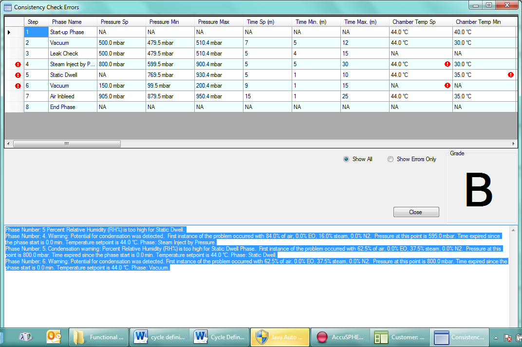
The system will provide a cycle consistency check in order to validate the cycle as per the rules outlined in section Rules for Monitoring Specs. At the end of each check the system will grade the cycle definition as follows:
-
A - Pass – OK to approve
-
B - Pass with warning – OK to approve
-
C - Conditional Pass – OK to approve with management role
-
F – Failed
Only cycles that have not failed will be available for approval and subsequent downloading to the controller for processing.
To check the consistency click Check Consistency
-
The Grade is displayed as well as the Errors.
-
The Step section can be sorted to Show All steps or Show Errors Only.
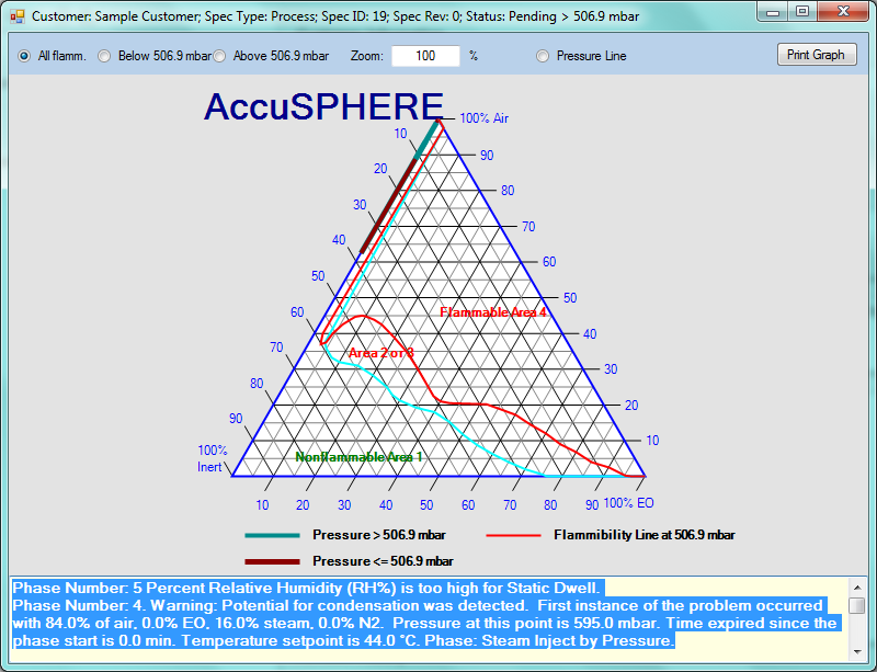
A Flammability Chart can be displayed and printed by clicking on the Flammability Chart button.
-
The chart can be displayed as All Flamm, Below 506.9 mbar or Above 506.9 mbar by selecting the radial button at the top of the screen.
-
The Pressure Line can be displayed by selecting the radial button at the top of the screen.
-
The graph can be printed by clicking on the Print Graph button on the top right of the screen.
Warning! The functions described in the following text cannot prevent the definition of an unsafe cycle resulting in an explosive mixture in one of the chambers. Only properly qualified personnel should be permitted to define a cycle. An improperly defined cycle may result in an explosive mixture. An explosive mixture in the chamber may result in property damage, personal injury or death.
Even if the chamber is considered not flammable, the gas mixture may be extremely toxic, dangerous to human health and to the environment. Therefore the plant must have proper procedures in place to deal with this hazard.
Negative Value Entry
Entry of negative values is NOT allowed in the following circumstances:
-
Equipment Phase Parameter Configuration
-
Error will be raised when load is transferred to PLC
-
-
Real time configurable parameters
Entry of negative values is allowed in the following circumstances:
-
Manual entry of values in Calibration module
Definitions
For the purposes of cycle consistency check only, the following definitions are used:
|
Term |
Definition |
|---|---|
|
Chamber gas is Flammable |
Any time EO is admitted into chamber (i.e. after EO Inject phase). |
|
Chamber gas is NOT Flammable |
EO was never admitted OR Calculated EO concentration is < 13.5 mg/l (or 25% LEL) |
Notes on Phases that use Steam
For the purposes of breathability and flammability checks, steam will be accounted for as follows:
-
Steam is considered an inert and non-breathable gas similar to Nitrogen.
-
Injecting steam is treated the same as Nitrogen Inject.
Notes on Loops
Loops that end on criteria other than duration or loop count, for the purposes of safety analysis, will always end on minimum count.
Rules for Customer Specs
Gas Partial Pressures in Continuous Steam Conditioning
At the beginning of the Continuous Steam Conditioning phase:
-
The current value of the Ethylene Oxide (EO) and Air partial pressure is stored.
-
The partial pressure of steam is changed to be the same as the pressure in the chamber in order to calculate condensation warnings and alarms.
At the end of the Continuous Steam Conditioning phase:
-
If the Duration Set-point is less than the Dynamic Conditioning Timer Minimum Duration [CyConsist_ContStCond_Duration], and/or the pressure set-point is greater than Dynamic Conditioning Timer max pressure [CyConsist_ContStCond_Pressure], then the chamber pressure will be distributed as follows:
-
If the pressure set-point is greater than the stored EO partial pressure, the EO partial pressure will be restored and the remaining chamber pressure will be distributed as follows:
-
If the remaining chamber pressure is greater than the stored air partial pressure, the air partial pressure will be restored and the steam partial pressure will be set to the remaining chamber pressure .
-
If the remaining chamber pressure is less than or equal to the stored Air partial pressure, then the air partial pressure will be set to the remaining chamber pressure and the Steam partial pressure will be set to 0.
-
-
If the chamber pressure is less than or equal to the stored EO partial pressure, then the EO partial pressure will be set to the chamber pressure and the partial pressures of Air and Steam will be set to 0.
-
-
If the Duration Set-point is greater than or equal to the Dynamic Conditioning Timer Minimum Duration [CyConsist_ContStCond_Duration], and the pressure setpoint is less than or equal to the Dynamic Conditioning Timer max pressure [CyConsist_ContStCond_Pressure], then the chamber pressure will NOT be re-set based on the stored partial pressure values.
Gas Partial Pressures in Dynamic Conditioning with Nitrogen
At the beginning of the Dynamic Conditioning with Nitrogen phase:
-
The current value of the Ethylene Oxide (EO) and Air partial pressures will be stored.
-
The partial pressure of nitrogen will be changed to be the same as the pressure in the chamber.
At the end of the Dynamic Conditioning with Nitrogen phase:
-
If the Duration Set-point is less than the Dynamic Conditioning Timer Minimum Duration [CyConsist_ContStCond_Duration], and/or the pressure set-point is greater than Dynamic Conditioning Timer max pressure [CyConsist_ContStCond_Pressure], then the chamber pressure will be distributed as follows:
-
If the Pressure Set-Point is greater than the stored EO partial pressure, the EO partial pressure will be re-set to the stored value and the remaining chamber pressure will be distributed as follows:
-
If the remaining chamber pressure is greater than the stored air partial pressure, the air partial pressure will be re-set to the stored value and the remaining chamber pressure will be placed in the nitrogen partial pressure.
-
If the remaining chamber pressure is less than or equal to the stored air partial pressure, then the air partial pressure will be set to the remaining chamber pressure and the nitrogen partial pressure will be set to 0.
-
-
If the Pressure Set-Point is less than or equal to the stored EO partial pressure, then the EO partial pressure will be set to the chamber pressure and the partial pressures of air and nitrogen will be set to 0.
-
-
If the Duration Set-point is greater than or equal to the Dynamic Conditioning Timer Minimum Duration [CyConsist_ContStCond_Duration], and the pressure setpoint is less than or equal to the Dynamic Conditioning Timer max pressure [CyConsist_ContStCond_Pressure], then the chamber pressure will NOT be re-set based on the stored partial pressure values.
Gas Partial Pressures in Dynamic Conditioning with Air
At the beginning of the Dynamic Conditioning with Air phase:
-
The current value of the Ethylene Oxide (EO) partial pressure will be stored.
-
The partial pressure of air will be changed to be the same as the pressure in the chamber
At the end of the Dynamic Conditioning with Air phase:
-
If the Duration Set-point is less than the Dynamic Conditioning Timer Minimum Duration [CyConsist_ContStCond_Duration], and/or the pressure set-point is greater than Dynamic Conditioning Timer max pressure [CyConsist_ContStCond_Pressure], then the chamber pressure will be distributed as follows:
-
If the Pressure Set-Point is greater than the stored EO partial pressure, the EO partial pressure will be re-set to the stored value and the remaining chamber pressure will be placed in the air partial pressure.
-
If the Pressure Set-Point is less than or equal to the stored EO partial pressure, then the EO partial pressure will be set to the chamber pressure and the air partial pressure will be set to 0.
-
-
If the Duration Set-point is greater than or equal to the Dynamic Conditioning Timer Minimum Duration [CyConsist_ContStCond_Duration], and the pressure setpoint is less than or equal to the Dynamic Conditioning Timer max pressure [CyConsist_ContStCond_Pressure], then the chamber pressure will NOT be re-set based on the stored partial pressure values.
Rules for Monitoring Specs
The Cycle Consistency rules for Monitoring Specs are the same as Customer Specs, except:
• Setpoints are not required.
• Abort Pressure for EO Inject is not required.
• Pressure Control Offset for Leak Check phase is not required.
Rules
Each cycle definition will be evaluated against the following criteria:
Value Validation
Failure to pass value validation will result in a grade of F. Each entered value will be validated as follows:
-
Each minimum tolerance was less than the set-point and each set-point or minimum value is less than the maximum.
-
Each value entered is within the limits of the range specified in the reference parameter data table.
-
Each dwell, continuous steam conditioning, and dynamic conditioning phase must have the following parameters specified (not empty and greater than 0):
-
Duration Set-point (Parameter 10).
-
-
Duration tolerance (Parameter 11) must be specified for Static Dwell phase.
-
Vacuum phase must have the following parameters specified (not empty and greater than 0):
-
Pressure set-point (Parameter 12)
-
Pressure increment (Parameter 18)
-
Duration for pressure increment (Parameter 19)
-
Minimum and maximum pressure tolerance (Parameter 14)
-
Minimum and maximum duration tolerance (Parameter 11)
-
-
Each inject phase must have the following parameters specified (not empty and greater than 0):
-
pressure set-point (Parameter 12)
-
Pressure increment (Parameter 18)
-
Duration for pressure increment (Parameter 19)
-
Minimum and maximum pressure tolerance (Parameter 14)
-
Minimum and maximum duration tolerance (Parameter 11) (except for Pressure Adjust where only maximum duration tolerance can be entered)
-
Steam Inject via RH must have RH set-point (Parameter 20) as well as RH tolerance parameters specified (Parameter 22)
-
Steam Inject via AH must have AH set-point (Parameter 25) as well as AH tolerance parameters specified (Parameter 27)
-
EO Inject via concentration must have the concentration set-point (Parameter 31) and tolerance specified (Parameter 33)
-
EO Inject via weight must have weight set-point (Parameter 36) as well as weight tolerance specified (Parameter 37)
-
-
Pressure tolerance specified in each dwell phase must:
-
Span pressure set-point of the previous inject phase
-
Overlap pressure tolerance of the previous dwell phase
-
-
Vacuum phase pressure set-point (Parameter 12) must be:
-
Lower than the closest preceding inject or Pressure Adjust phase pressure set-point
-
-
Inject phase pressure set-point (Parameter 12) must be:
-
Higher than the closest preceding Vacuum or Pressure Adjust phase pressure set-point
-
When EO has been admitted to the chamber, the inject pressure set-point must be smaller than the ambient pressure less a configurable offset
-
-
EO Inject and Dwell Phase parameters must obey the following rules:
-
The abort pressure set-point (Parameter 83) must be defined
-
The abort pressure must be smaller than the ambient pressure minus a configurable offset
-
The abort pressure must be smaller than the maximum alarm pressure tolerance (if this feature is enabled for your site).
-
-
Cycle Consistency check for EO make-up:
-
EO Dwell phase: if [Parameter 86] (differential used for pressure control) or [Parameter 32] (differential used in determining gas valves opening) are greater than zero, the “maximum number of make-ups” [Parameter 54] must also be greater than zero, otherwise the cycle will be graded F.
-
EO Dwell with Nitrogen Make-up Phase: if [Parameter 86] (differential used for pressure control) is greater than zero, the “maximum number of make-ups” [Parameter 54] must also be greater than zero, otherwise the cycle will be graded F.
-
-
Cycle Consistency Check for Steam Inject by Pressure
-
Either pressure set-point [Parameter 12] or pressure change set-point [Parameter 13] can be set for this phase but not both. Cycle will be graded F if both are set.
-
-
Cycle Consistency Check for Conditioning Dwell by Pressure
-
If pressure set-point [Parameter 12] is specified in Conditioning Dwell by Pressure, it must have the following properties:
-
The value must be the same as the pressure set-point [Parameter 12] of the previous phase
-
May not be specified if the previous Steam Inject by Pressure phase is programmed using the Change in Pressure Set-point [Parameter 13]
-
-
-
Chamber temperature set-point (Parameter 2) must be less than or equal to the cooling temperature set-point (Parameter 58)
-
If chamber temperature set-point is specified (Parameter 2), then the minimum and maximum chamber temperature alarm tolerances (Parameter 3) must be specified as well
-
If jacket temperature set-point (Parameter 6) is specified, then the minimum and maximum jacket temperature alarm tolerances (Parameter 7) must be specified as well
-
Either RH set-point (Parameter 20) or AH set-point (Parameter 25) can be set for the Conditioning Dwell via RH/AH phase, not both.
-
Either pressure set-point (Parameter 12) or pressure change set-point (Parameter 13) can be set for the EO Inject via Pressure phase.
-
If pressure set-point (Parameter arameter 12) is specified in the EO Dwell or EO Dwell with Nitrogen Make-up phase, it must have the following properties:
-
The value must be the same as the pressure set-point of the previous phase
-
May not be specified if the previous EO Inject phase uses the change in pressure set-point parameter 13.
-
Condensation Warning
Cycles where potential for condensation is determined will be graded B.
Condensation will be determined as follows:
-
Lower of the jacket (Parameter 6) or chamber temperature set-point (Parameter 2) will be used
-
Steam partial pressure will be used
-
Condensation warning will be raised for phases based on the lower temperature set-point and partial pressure of steam, as derived from the steam table.
Phase Interdependency
If the following rules are not met, the cycle will be graded F:
-
The first phase shall be the header phase
-
The second phase shall be the start-up phase
-
Before EO gas is allowed into the chamber, a minimum 5 minute Leak Check phase will be required for all specifications with EO Inject via Pressure/Concentration/Weight (only applies if this feature is enabled for the site)
-
Before EO is allowed into the chamber air-concentration must be less than 12% (if this feature is enabled for your site)
-
Vacuum phase may not be inserted between any EO Inject (via Pressure/Concentration/Weight) and EO Dwell (or EO Dwell with Nitrogen Make-up), if this feature is available for your site.
-
Before any Air In-bleed, or Dynamic Conditioning with Air phase can start:
-
EO Concentration must be less than 27 mg/l
-
-
Before the last Air In-bleed phase can start, one of the following points must be true:
-
EO Concentration must be less than 13.5 mg/l or
-
Chamber is not Flammable
-
-
Before the cycle is considered complete, all of the following points must be true:
-
50% of chamber gas volume must be filled with air (if this feature is enabled for your site).
-
Chamber must not be Flammable
-
Final pressure set-point for the last Air In-bleed phase must be 14.2 (-.1/+.6) PSIA
-
-
Any loop phase must have at least two sub-phases
-
No EO Inject can follow a Nitrogen Wash Loop
-
No Nitrogen Inject, EO Inject (via Pressure/Concentration/Weight), Steam inject (via Pressure/RH/AH), EO Dwell or EO Dwell with Nitrogen Make-up can follow an Air Wash Loop
-
Keyword 27 which allows transferring loads to PLC when chamber door(s) is/are closed cannot be set to TRUE if the cycle has an EO Inject or EO Dwell phase, see Linked Loads.
Management Approval Requirement
If the following requirements are not met, the cycles will be C or F graded:
-
If a cycle includes EO admission as well as Continuous Steam Conditioning, or Dynamic Conditioning with Nitrogen phase preceding it, a warning will be generated if:
-
At the beginning of Continuous Steam Conditioning, or Dynamic Conditioning with Nitrogen phase, more than 3% of air is still a part of the gas mixture and continuous steam conditioning pressure set-point is less than 3 PSIA the cycle will be C graded and following message will be indicated to the user:
Warning! Cycle consistency rule for %Air before a Continuous Steam Conditioning, or Dynamic Conditioning with Nitrogen phase was not met. Cycle to be verified by employee with Management role.
-
At the beginning of Continuous Steam Conditioning, or Dynamic Conditioning with Nitrogen phase, more than 3% of air is still a part of the gas mixture and Continuous Steam Conditioning, or Dynamic Conditioning with Nitrogen pressure set-point is greater than 3 PSIA, the cycle will be graded F.
-
-
If at the end of the cycle:
-
Chamber gas contains less than 50% air by volume the cycle will be F graded.
-
Chamber gas contains between 50% and 90% air by volume cycle will be C graded and following message will be indicated to the user:
Warning! Cycle Consistency Rule for % Air in Chamber has not been met. Cycle to be verified by employee with Management role.
-
-
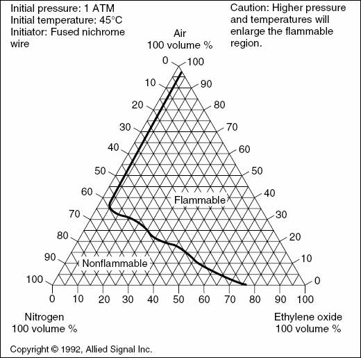
EO flammability will be calculated based on the 1 ATM chart below if the chamber pressure is between ½ ATM and 1 ATM. If a cycle is potentially flammable, management approval will be required. For detailed warning message please see section below.
-
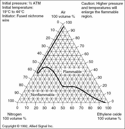
EO flammability will be calculated based on the ½ ATM chart below if the chamber pressure between 0 ATM and ½ ATM. If a cycle is potentially flammable, management approval will be required. For detailed warning message please see section below.
Cycle Consistency User Feedback
Each cycle consistency warning will include the following information:
-
Which step the warning occurred in
-
Which phase
-
Pressure at which the warning occurred
-
Time into the step when the warning occurred
-
Percent gas concentration of:
-
EO
-
Inert gas
-
Air
-
-
Flammability warnings will also indicate which cycle pressure curve (either pressure curve 3 or 4 – see below) the warning occurred. The flammability chart will be displayed (see sample figures below).
Flammability Pressure Curves
For the purposes of flammability analysis, the following cycle pressure curves are considered:
-
Cycle Pressure Curve 1) Below both the ½ ATM and 1 ATM flammability curve and therefore considered non-flammable – no action needed;
-
Cycle Pressure Curve 2) Between the two flammability curves and the cycle pressure is less than ½ ATM and therefore no flammability evaluation is needed
-
Cycle Pressure Curve 3) Between the two flammability curves and the pressure is more than ½ ATM and therefore an evaluation is needed. The cycle definition will be C graded and the following massage will be shown to the user:
Warning! Cycle pressure curve entered the region between the two flammability curves. Cycle to be verified by employee with a management role.
-
Cycle Pressure Curve 4) Above both flammability curves – considered flammable. The cycle definition will be C graded and the following message will be shown to the user:
Warning! Cycle Consistency Rule for LEL / Flammability has not been met. Cycle to be verified by employee with a management role.
The Cycle Consistency Check will display flammability (see Figure 35) of the defined cycle on the NFPA 560 EO flammability chart as it applies to 1 and 1/2 ATM chamber pressure curves:
Cycle Consistency Rules
The following bolded condition will be added for the Leak Check phase:
-
The Leak Check phase must be programmed in the cycle if:
-
CyConsist_LeakCheckDisabled System Parameter is FALSE and;
-
Specification includes EO Inject via Pressure/Concentration/Weight phase (Phase IDs 12, 13, 14) and;
-
Inject phase pressure set-point is less or equal to atmospheric pressure
-
The following rules will be added for the Super-Atmospheric EO Dwell phase:
-
The Super-Atmospheric EO Dwell phase must be programmed in the cycle if:
-
CyConsist_EODwellLeakCheckDisabled System Parameter is FALSE and;
-
Specification includes EO Inject via Pressure/Concentration/Weight phase (Phase IDs 12, 13, 14) and;
-
Inject phase pressure set-point is greater than atmospheric pressure.
-
-
If pressure set-point [Parameter 12] is specified:
-
The value must be the same as the pressure set-point of the previous phase
-
The value must be greater than the atmospheric pressure
-
The value must NOT be defined if the preceding EO Inject phase uses the Change in Pressure Set-point [Parameter 13]
-
-
If pressure set-point [Parameter 12] is NOT specified:
-
The final pressure of the preceding phase must be greater than the atmospheric pressure
-
-
The pressure tolerance [Parameter 14] must:
-
Span pressure set-point [Parameter 12] of the previous inject phase
-
Overlap pressure tolerance of the previous phase
-
-
Abort pressure must obey the following:
-
The abort pressure set-point [Parameter 83] must be defined
-
The value must be greater than the ambient pressure plus a configurable offset (System Parameter Pressure_Offset).
-
The value must be greater than the phase minimum pressure tolerance [Parameter 14 Min]
-
-
The Duration Set-point [Parameter 10] and tolerance [Parameter 11 Min] must be defined and must have a value greater than CyConsist_MinEODwellLeakCheckDuration System Parameter
-
The following parameters must either all be defined, or none can be defined:
-
Pressure Stabilization Delay [Parameter 257] and *** the rest is missing in the original lp sept 7 2024
-
Warning! The functions described in the preceding text cannot prevent the definition of an unsafe cycle resulting in an explosive mixture in one of the chambers. Only properly qualified personnel should be permitted to define a cycle. An improperly defined cycle may result in an explosive mixture. An explosive mixture in the chamber may result in death, personal injury or property damage.
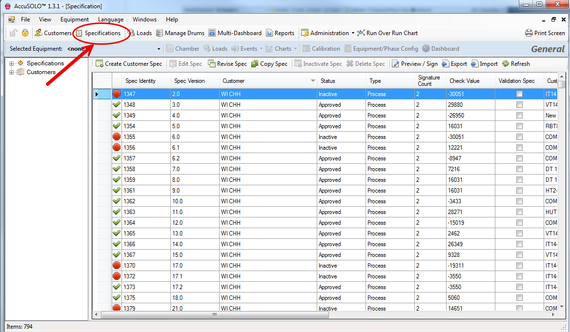
Create New Specification
-
To access the Specification Module click Specifications.
-
Click Create Customer Spec.
-
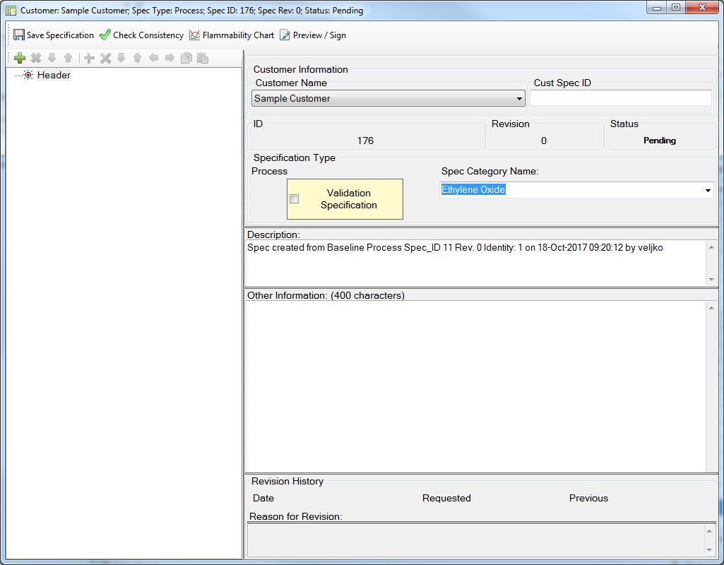
Select a Customer Name from the drop-down list.
-
Enter a Customer Specification ID.
-
Click Save Specification.
-
With the Header node selected, click the “Add Stage” + icon to create a stage.
-
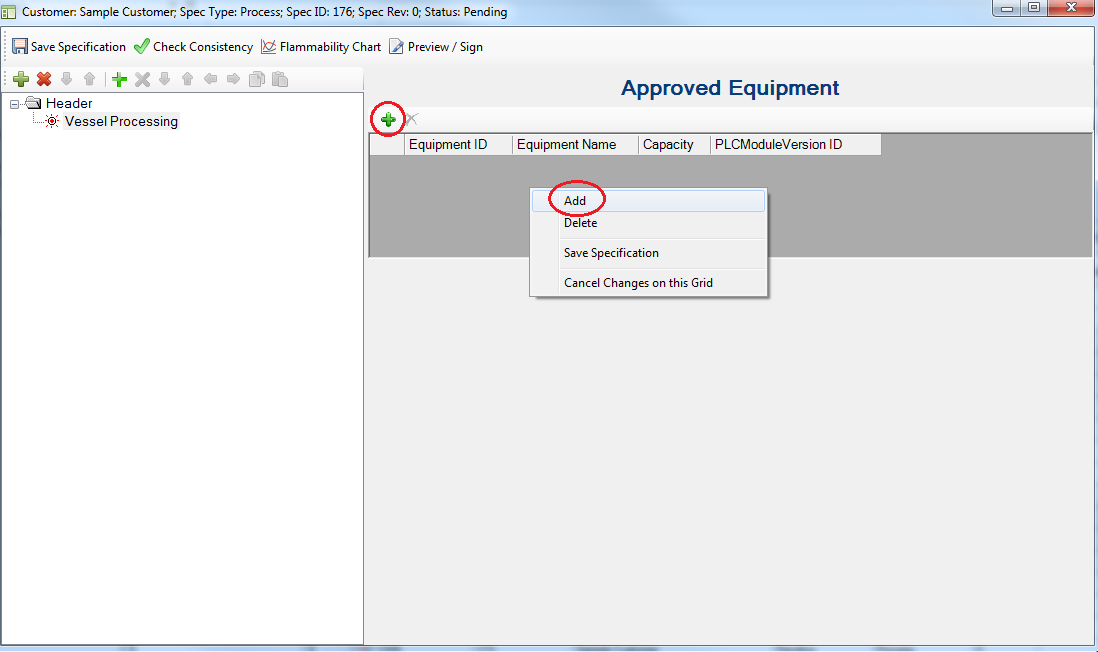
From the Select Stage pop-up window select a stage from Available Stages drop down.
-
For chamber, select Vessel Processing.
-
AccuSOLO is available for Preconditioning and Aeration as well.
Vessel Processing Stage Setup
-
Highlight Vessel Processing and right-click in the table under “Approved Equipment” and pick “Add”, or click the + button, to add a chamber to the specification:
-
Once the equipment has been added, click on the
 icon to add a step. A pop-up will be presented allowing you to select the desired phase from the drop-down menu.
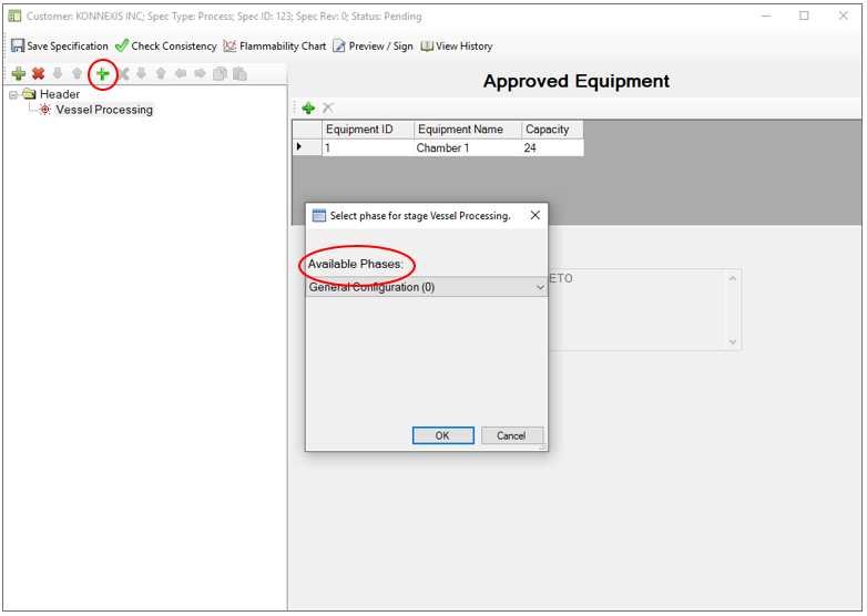
-
From the Select Phase pop-up select the required Phases from the Available Phases drop-down.
-
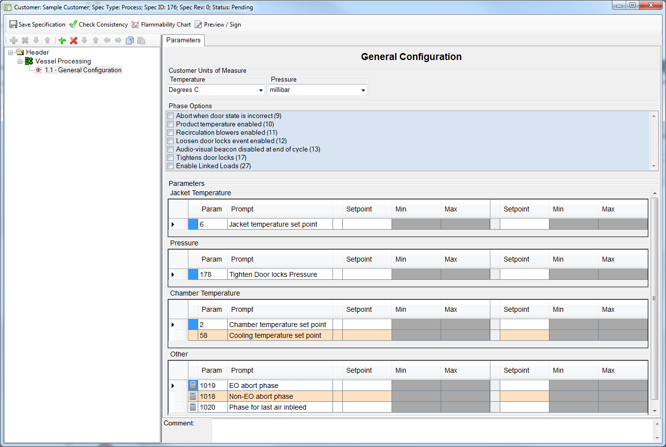
Add the General Configuration phase first so that you can define general parameters and phase options:
-
To move an existing phase up or down in the cycle sequence, select the phase you wish to move and then use the
 buttons.
 -
To copy a phase and paste it at a specific cycle sequence position:
-
Select the phase you wish to copy and then click the copy step icon

-
Select the phase after which you wish to paste the phase you have just copied and then click the paste step icon
 . The phase will be inserted.
-
Tip: You can assign a parameter value to all the subsequent phases that you have defined in your cycle definition by clicking the row of the parameter and clicking “Apply same value to all steps.”
Note that this will only assign the value to phases that occur after the currently selected phase. For example, to assign the same jacket temperature set-point value to all of the phases in your cycle, right click the “Jacket temperature set point” row in the Start-up phase and select “Apply same value to all steps.” Now all of the phases that were defined after the start-up phase will obtain the same jacket temperature set-point value.
Creating Loops
-
Click the + icon and add the desired loop phase.
-
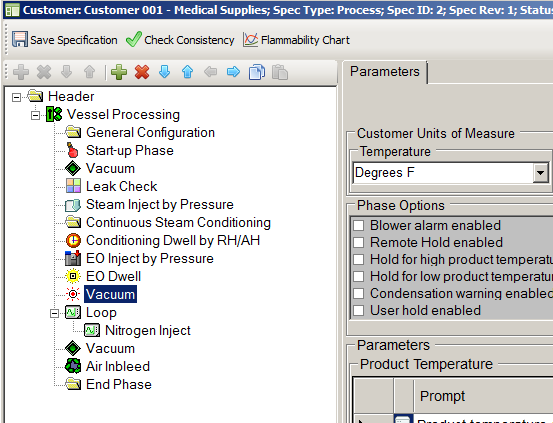
Add the first phase that you wish to put inside the loop (i.e. the sub-phase) and position it in the sequence so that it sits just before the loop phase. In the example below, the Vacuum phase sits just before the loop phase.
-
Click the
 icon to move the Vacuum phase into the loop phase. The result is illustrated in the following screenshot:
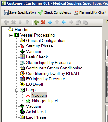
-
To remove a phase from a loop, select the phase to be removed and click the
 icon.
icon.
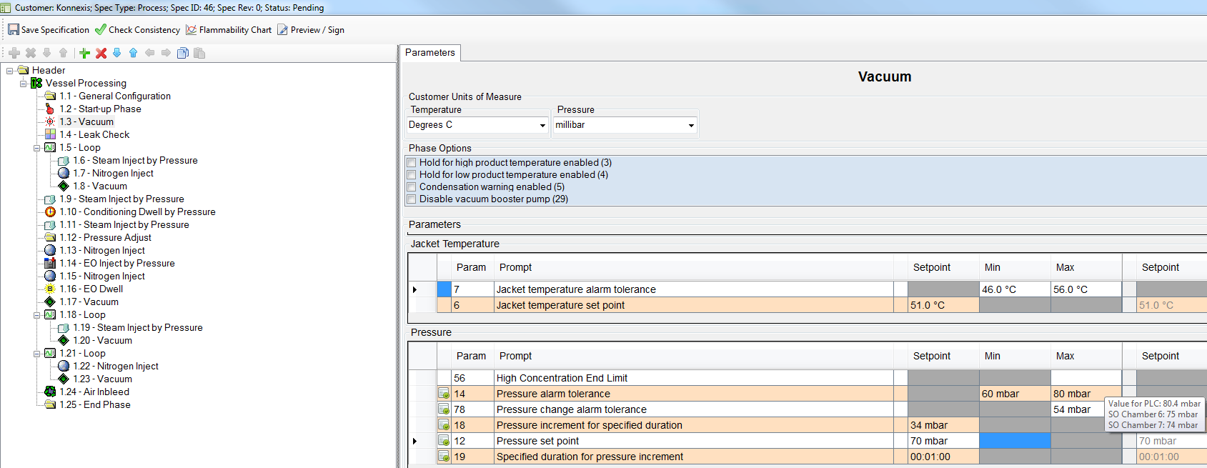
Offset Parameters in Tooltips
When hovering the mouse over certain parameters, a tooltip will show the true value of the parameter after it is adjusted by each approved equipment’s corresponding offset parameter value.
For example, consider defining pressure alarm tolerance for the Vacuum phase:
-
One of the Vacuum phase completion criteria state that the phase will complete when pressure is less than or equal to the Maximum Pressure Alarm Tolerance [Parameter 14 Max] minus the Equipment/Phase Offset Parameter 69 (maximum pressure offset for phase end), and elapsed phase time is greater than or equal to maximum duration tolerance [Parameter 11 Max] less 1 minute (see Vacuum phase completion criteria section Phase Completion)
-
This means that the value that you program for the Vacuum phase maximum pressure alarm tolerance [Parameter 14] will be adjusted by the chamber’s maximum pressure offset for phase end value in Parameter 69. The tooltip will show this adjusted value for each of the chambers in the approved equipment list for the specification.
-
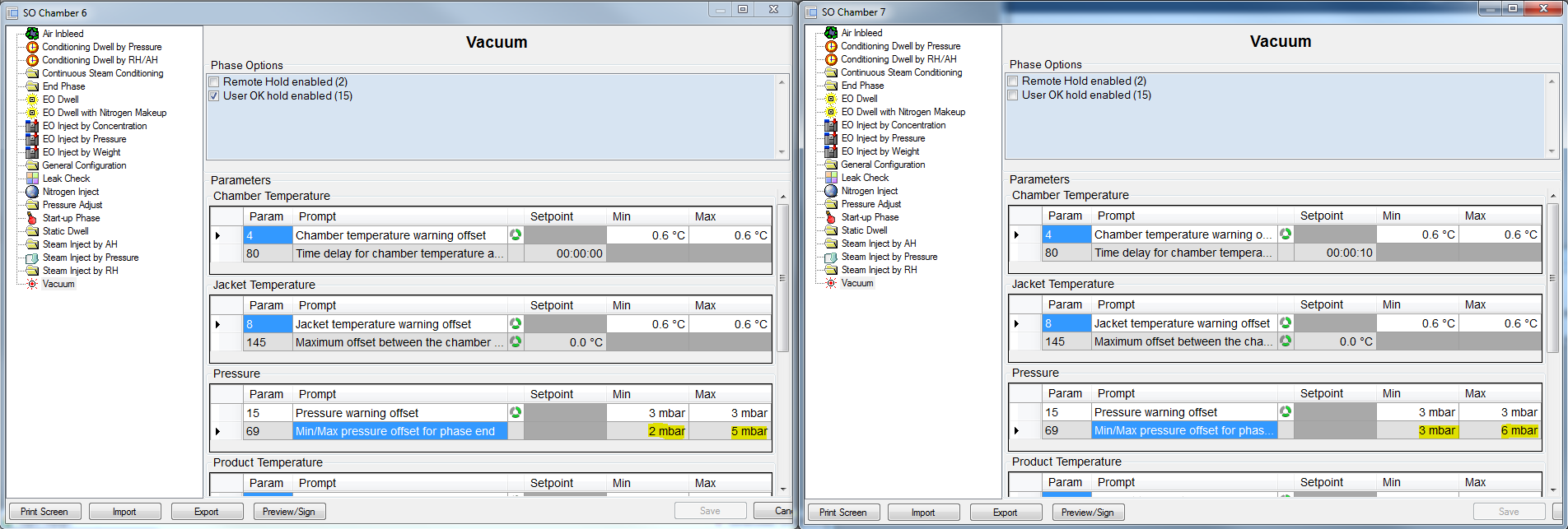
In the following example, two chambers have different values for Parameter 69 maximum (5 mbar and 6 mbar):
-
Therefore the Vacuum phase maximum pressure tolerance value of 80 mbar is adjusted by 5 mbar and 6 mbar to give 75 mbar and 74 mbar, respectively, and as such is shown on the tooltip:
Approving (Electronically Signing) Specifications
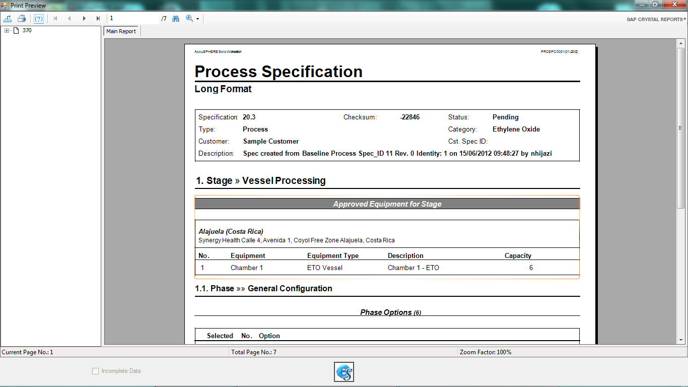
A pending specification can be approved by highlighting the specification and clicking the Preview/Sign button on the toolbar.
-
The process specification long format report is displayed.
-
To sign off on the report click the e-sign button,
 .
.
-
The first time a user electronically signs a document they are required to verify their identity.
-
Read the statement and click Accept.
-
This is only required the first time a user electronically signs.
-
-
Enter your password.
-
Depending on your configuration, the report may require more than one e-signature to be approved.
-
The last page of the report displays a Signature Manifest. The section is populated with the Name, date and time of 1st signature.
-
After the required number of users have applied their electronic signatures, the report is converted to PDF and all signatures are displayed in the Signature Manifest.
-
The status of the Specification will change to Approved.
-
Loads can now be built against this specification after which they can be downloaded to the process controller.
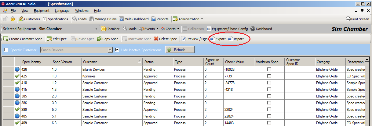
Importing and Exporting Specifications
It is possible to import and export specifications via an xml file.
-
When importing a specification xml file, the application will only import parameters that exist in the system.
-
Equipment assignment will NOT be imported into the vessel processing stage.
-
The customer ID configuration will NOT be imported.
To import/export specifications, navigate to the Specifications grid and use the “Import” and “Export” buttons on the toolbar:
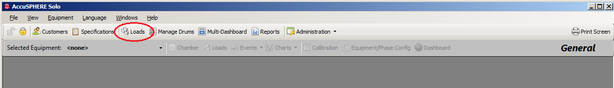
Loads
Creating Loads
Once a cycle definition is approved and passes a cycle consistency check (i.e. does not receive an ‘F’ grade), a load can be built for the items requiring such a cycle definition. Each load obtains its proper and unique Load ID.
-
Create the load in the system by clicking the Load button located in the menu bar and entering the product load information (note that some of the fields are optional):
-
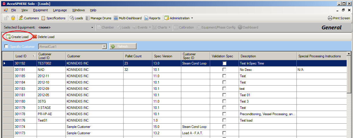
The Loads grid will be presented showing all loads that exist in the system
-
Click the Create Load button to create a new load:
-
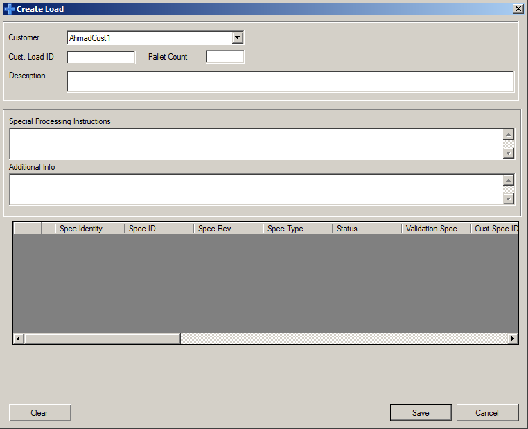
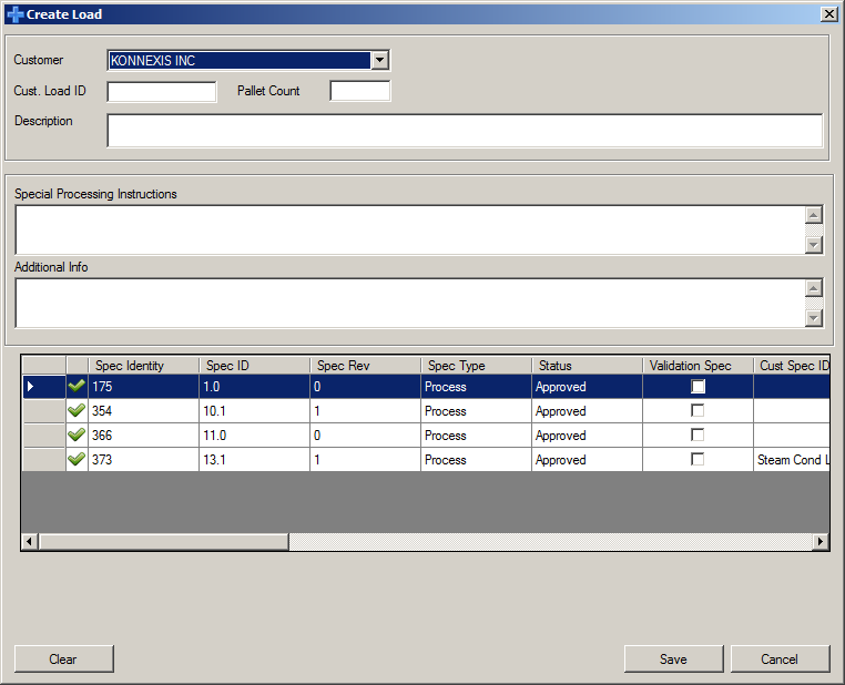
The Create Load pop-up form will be presented:
-
Selecting a customer will display a list of Approved specifications for that customer against which a load can be built:
-
Enter the remainder of the product load information (note that some of the fields are optional) and click Save. The Load will be created.
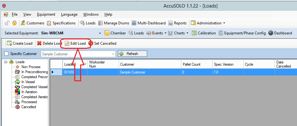
Editing Loads
With the appropriate privilege level, a load can be edited from the Loads grid. Select the load and then click the “Edit Load” button. Note that if the load is past the “Non Process” stage, the customer and specification identity cannot be edited.
After a load has been transferred, it will *NOT* be possible to change the following Load information regardless of any user role:
-
Process Specification
-
Aeration Specification
-
Product Types
-
Number of Packages (Package Count and Dummies Count) when Customer Feature CFLCT1 is configured
Downloading Loads to the Process Controller
The following conditions must be satisfied before the system will allow a load to be downloaded to the system for processing:
-
Chamber door must be open
-
Chamber must be in dormant sequence
-
The current Load ID in the controller must be zero or the Load ID indicated has already been completed.(i.e. no load has already been downloaded to the controller)
-
Chamber devices must all have valid calibrations (i.e. no device calibrations on the chamber can be expired)
-
Chamber is capable to run the cycle.
-
Cycle definition is approved.
-
Cycle definition has not been altered since it has been approved.
-
*Note: transferring a load to the PLC will fail if the chamber configuration is not approved unless the user-interface option “Allow load transfer with pending chamber configuration” is set.
-
For information on how to run a load with pending Equipment/Phase Chamber Configuration, see Running Loads with Pending Configuration.
-
To download the load to the process controller:
-
Select the appropriate chamber from the selected equipment dropdown menu and then click the Loads button:
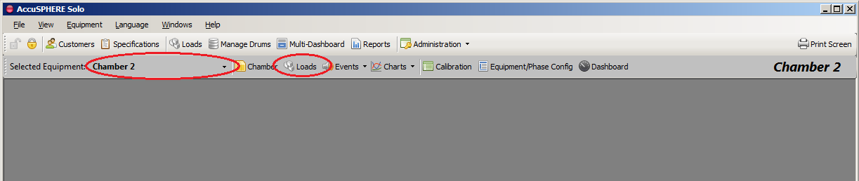
-
A list of available loads for the selected equipment will be presented:
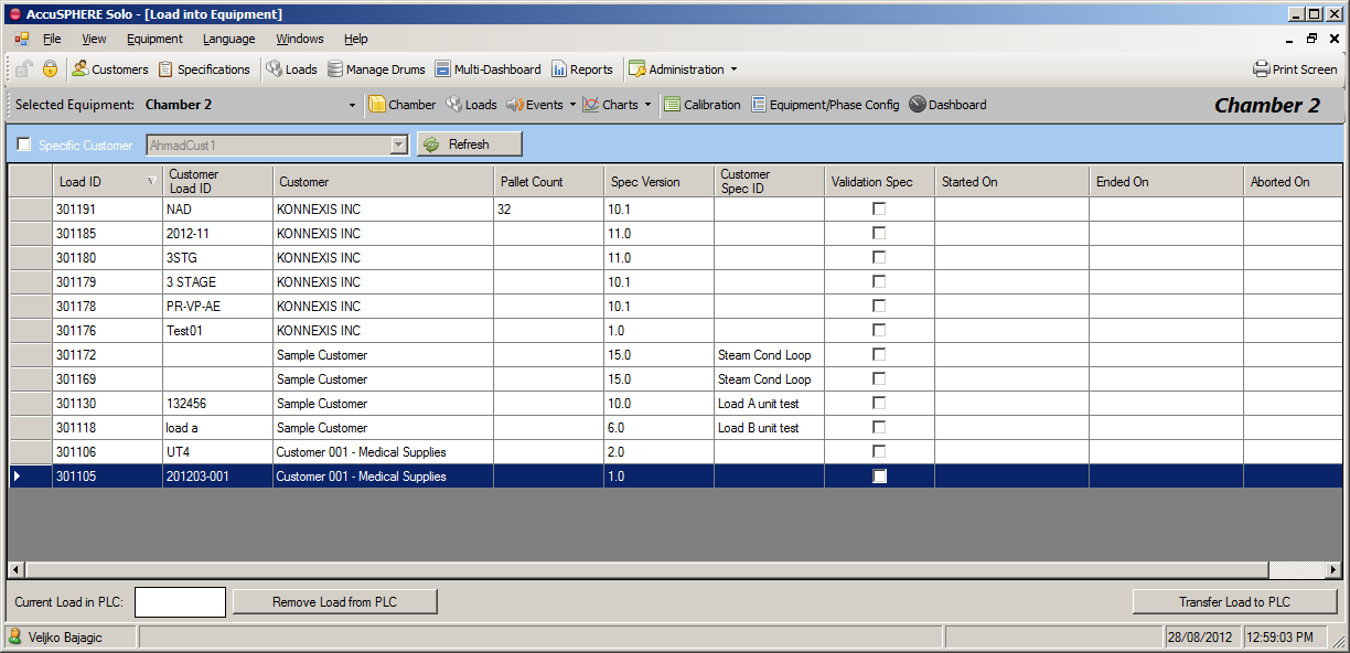
-
Select the load you wish to send to the controller and click the Transfer Load to PLC button. The system will perform the chamber capability checks as described in section Chamber Capability Checks. The equipment must also not have any devices for which the calibration has expired (see section Expired Calibrations for more information).
-
Once the system informs you that the load has been successfully transferred to the PLC, you can start the load:
-
Physically close the chamber door
-
From the specific Chamber screen, click the Start button at the bottom of the screen
-
Every load can only be processed once
-
-
When a cycle has been started, it will automatically proceed through the sterilization phases until the entire cycle is completed.
-
When the cycle has been completed and the door has been opened, the system considers the load complete.
Deleting a Load from the Process Controller
The system will allow operators to delete loads from the process controller as long as the chamber is in the dormant sequence and the cycle for that load has not yet been started.
Note: Deleting a load from the process controller will NOT delete the load from the database, i.e. the load will still be available for processing at a later time.
To delete a load from the process controller, navigate to the loads screen for the selected equipment (as described in section Downloading Loads to the Process Controller) and click the Remove Load from PLC button.
Linked Loads
The system allows tracking of multiple successive loads (linked loads):
-
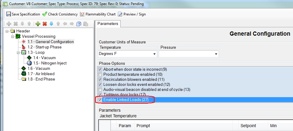
General Configuration specification Keyword 27 (Enable Linked Loads): when set to TRUE for a particular cycle, then any loads built against that cycle can be transferred to the PLC even when the chamber door(s) is/are closed. For example, this functionality can be used to run additional washes after a cycle has completed, door was never opened, and the EO concentration in the chamber has gone up in the meantime.
To enable the linked loads functionality, set Keyword 27 to TRUE for the cycle.
Note: As per cycle consistency rules, Linked Loads Keyword 27 cannot be set to TRUE for any cycle that has an EO Inject or EO Dwell phase.
-
The procedure for the operator is as follows:
-
When the cycle reaches the End Phase, operator clicks Unload to complete the cycle and put chamber into Dormant (chamber door is still closed)
-
Operator builds a new load where Keyword 27 is set to TRUE
-
When this load is run, the system will automatically link this load to the previous load that was run in the chamber.
-
The Run Record of the previous load will show the “Linked Load ID” of the subsequent load in which Keyword 27 was true.
-
Previewing/printing a Run Record will automatically also open/print the run record of the subsequent linked load
-
-
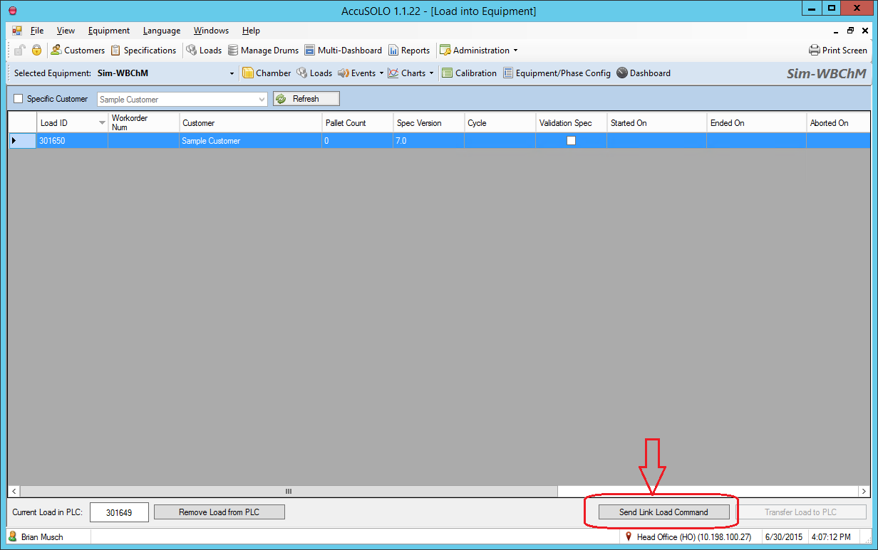
When the new load is selected in the Loads grid for the chamber, operator will click a new button “Send Link Load Command” (this button will only become available/enabled if the Keyword 27 is set to TRUE for the selected load). This will enable the “Transfer Load to PLC” button.
-
-
Operator will click “Transfer Load to PLC” button and the load will be transferred to the PLC and then started. An event will be raised.
When the new load is started, the system will update the OLD load process run “Header” with the new linked load process run ID.
Note the following:
-
The ability to transfer the new load with door closed will be cancelled if:
-
No load is sent through within 1 minute of clicking the “Allow Transfer with Door Closed” – client sends a command with the load ID
-
User clicks on a different row (i.e. a different load in the grid) – PLC will hold the state of which load ID is allowed to be transferred (for 1 minute only)
-
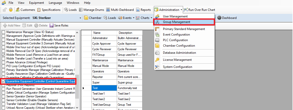
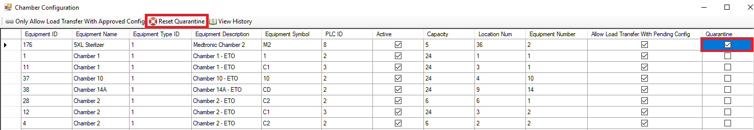
Equipment Quarantine State
It is possible to put the equipment (chamber or preconditioning/aeration) into a Quarantine State:
-
When equipment is in Quarantine State, the following rules are enforced by the software:
-
Only users with ControlQuarantineEquipment role have access to the equipment’s Start/Run button.
-
If a cycle has already started, the equipment is put into Quarantine State, and the chamber goes into Hold/Stop, only a user with ControlQuarantineEquipment role is allowed to put it back into Run mode.
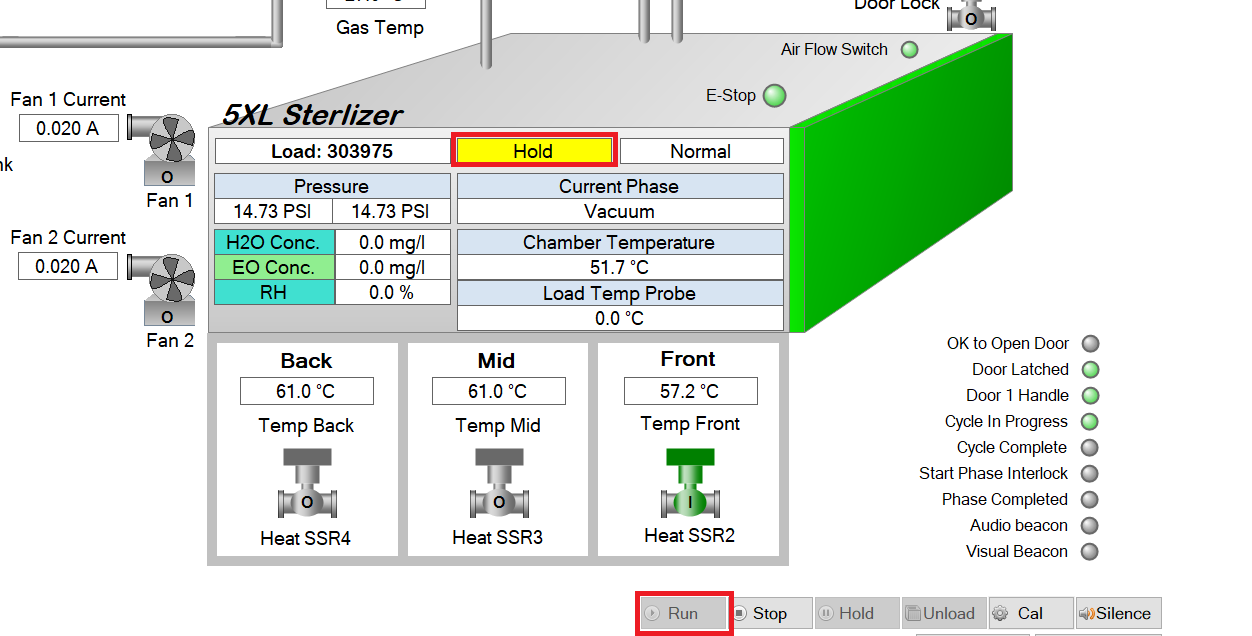
-
-
System only allows transfer of loads with a specification belonging to a configured Quarantine Customer, e.g. create a new customer called Engineering Maintenance and configure it to be the “Quarantine Customer”.
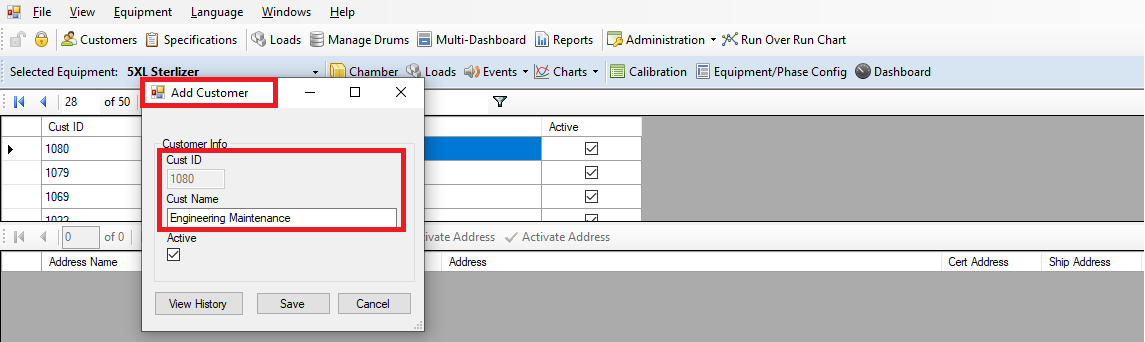
-
Quarantine Customer is available in System Configuration.

-
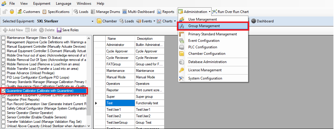
If a load with Quarantine Customer is running and the equipment is in Quarantine State, users with the role CalibrateWithQuarantineLoad are allowed to perform calibration while the load is running.
-
Unloading functionalities are unaffected by this state (e.g. removing/unloading a load from a room).
Loads with Validation Specifications
-
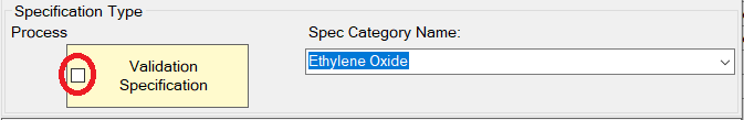
If a load is built with a specification that has the “Validation” flag set:
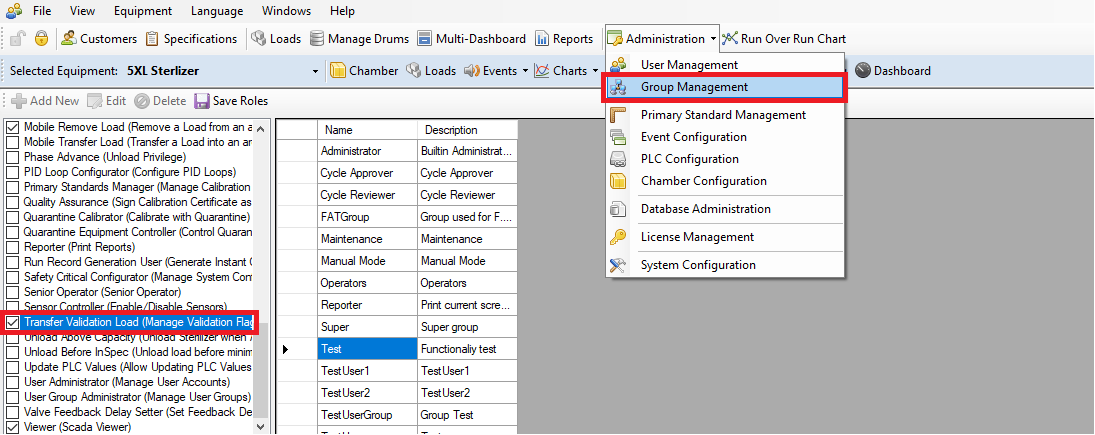
Only users with the role TransferValidationLoad will be able to transfer this load into equipment.
-
Both TransferValidationLoad and ControlQuarantineEquipment roles will be required to run a validation cycle while equipment is in Quarantine State.